#include <visp3/ustk_core/usPixelMeterConversion.h>
Static Public Member Functions | |
| static void | convert (const usImagePostScan2D< unsigned char > &image, const double &u, const double &v, double &x, double &y) |
| static void | convert (const usImagePostScan3D< unsigned char > &image, const double &u, const double &v, const double &w, double &x, double &y, double &z) |
Detailed Description
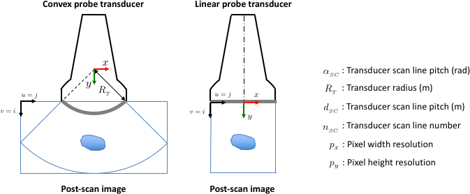
Conversion between a pixel position in the ultrasound image and the real position in meters.
- Warning
- Be sure you correctly filled your acquisition settings (probe radius, scan line pitch, etc...). Those parameters are used in the conversion !
The following image shows the correspondance between frames (u,v) and (x,y) for post-scan 2D images:
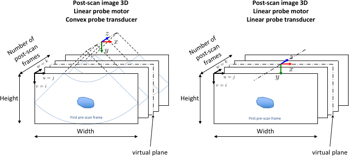
The following image shows the correspondance between frames (u,v,w) and (x,y,z) for post-scan 3D images with linear motor:
Definition at line 61 of file usPixelMeterConversion.h.
Member Function Documentation
◆ convert() [1/2]
|
static |
Conversion for 2D post-scan images.
- Parameters
-
[in] image 2D Post-scan image with settings well filled. [in] x Position in meters along x axis to convert. [in] y Position in meters along y axis to convert. [out] u Converted position in pixels along x axis. [out] v Converted position in pixels along y axis.
- Warning
- Make sure you completed the following transducer settings and the image settings before the conversion. Settings needed in case of linear transducer : -The image dimensions (normally set when you filled your image). -The height and width resolutions.
Settings needed in case of convex transducer : -The image dimensions (normally set when you filled your image). -The height and width resolutions. -The transducer radius (in meters). -The scan line number : number of scan lines used when you acqired the image. -The scan line pitch : angle (radians) between two successive scan lines in acquisition.
- Examples
- tutorial-servo-target-confidence.cpp, tutorial-servo-target.cpp, and tutorial-ultrasonix-servo-target-confidence.cpp.
Definition at line 61 of file usPixelMeterConversion.cpp.
References usImagePostScan2D< Type >::getHeightResolution(), usTransducerSettings::getScanLineNumber(), usTransducerSettings::getScanLinePitch(), usTransducerSettings::getTransducerRadius(), usImagePostScan2D< Type >::getWidthResolution(), and usTransducerSettings::isTransducerConvex().
◆ convert() [2/2]
|
static |
Conversion for 3D post-scan images.
- Parameters
-
[in] image 2D Post-scan image with voxels spacings, transducer settings and motor settings well filled. [in] x Position in meters along x axis to convert. [in] y Position in meters along y axis to convert. [in] z Position in meters along z axis to convert. [out] u Converted position in pixels along x axis. [out] v Converted position in pixels along y axis. [out] w Converted position in pixels along z axis.
- Warning
- Make sure you completed the following transducer settings, the motor settings, and the image settings before the conversion. Settings needed in case of linear transducer and linear motor : -The image dimensions (normally set when you filled your image). -The 3 elements spacing (x,y and z).
Settings needed in case of linear transducer and tilting motor : -The image dimensions (normally set when you filled your image). -The 3 elements spacing (x,y and z). -The motor radius. -The frame number : number of frames you acqired to get this post-scan image. -The frame pitch : angle (radians) between two successive frames in acquisition.
Settings needed in case of convex transducer and linear motor : -The image dimensions (normally set when you filled your image). -The 3 elements spacing (x,y and z). -The transducer radius (in meters). -The scan line number : number of scan lines used when you acqired the image. -The scan line pitch : angle (radians) between two successive scan lines in acquisition.
Settings needed in case of convewx transducer and tilting motor :
Definition at line 111 of file usPixelMeterConversion.cpp.
References usImagePostScan3D< Type >::getElementSpacingX(), usImagePostScan3D< Type >::getElementSpacingY(), usImagePostScan3D< Type >::getElementSpacingZ(), usMotorSettings::getFrameNumber(), usMotorSettings::getFramePitch(), usMotorSettings::getMotorRadius(), usMotorSettings::getMotorType(), usImage3D< Type >::getNumberOfFrames(), usTransducerSettings::getScanLineNumber(), usTransducerSettings::getScanLinePitch(), usTransducerSettings::getTransducerRadius(), usImage3D< Type >::getWidth(), usTransducerSettings::isTransducerConvex(), usMotorSettings::LinearMotor, and usMotorSettings::TiltingMotor.